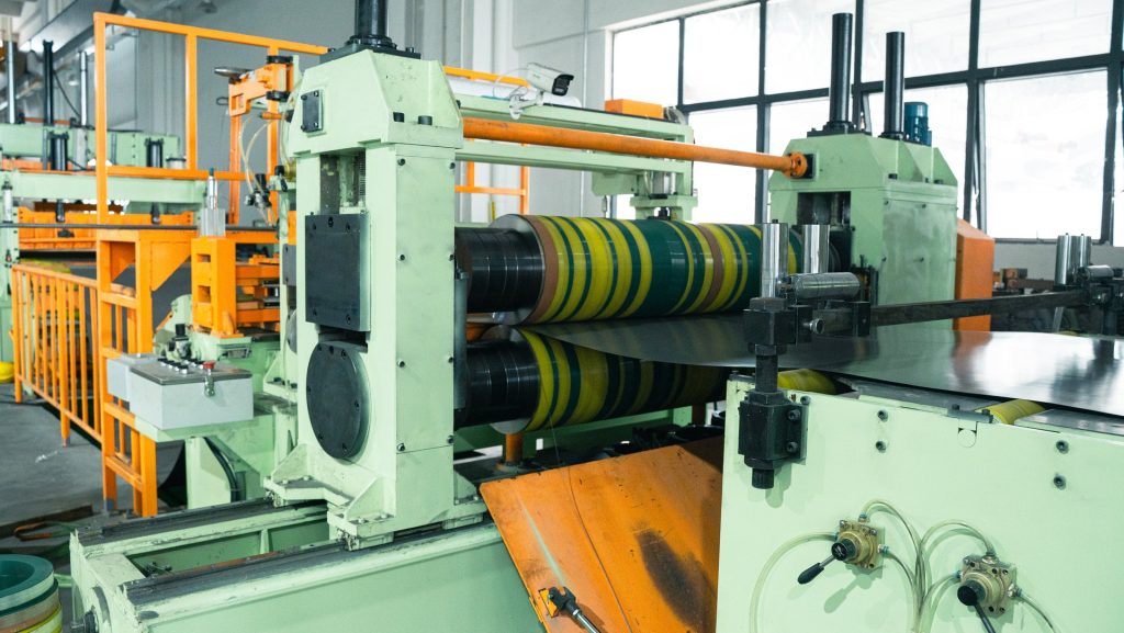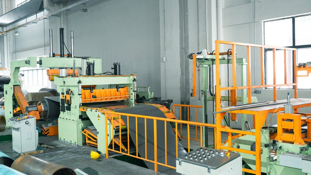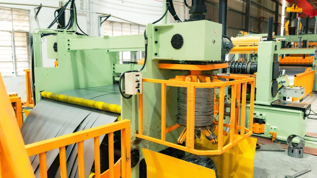
Slitter knife clearance is one of the first settings investigated when a slit edge develops excessive burr, tearing or an unstable fracture zone. It is important, but it is not the only variable. Knife overlap, tooling sharpness, shaft condition, spacer accuracy, strip guidance, material strength and thickness all influence how the edge separates. Treating burr as a single-setting problem can move the symptom without correcting its cause.
On a coil slitting line, the objective is not merely to divide a wide strip. Each narrow strip must meet the agreed width and edge requirements, pass through separation and tension without damage, and rewind into a usable coil. A practical setup method therefore connects the knife stack with the full material path.
Clearance and overlap perform different jobs
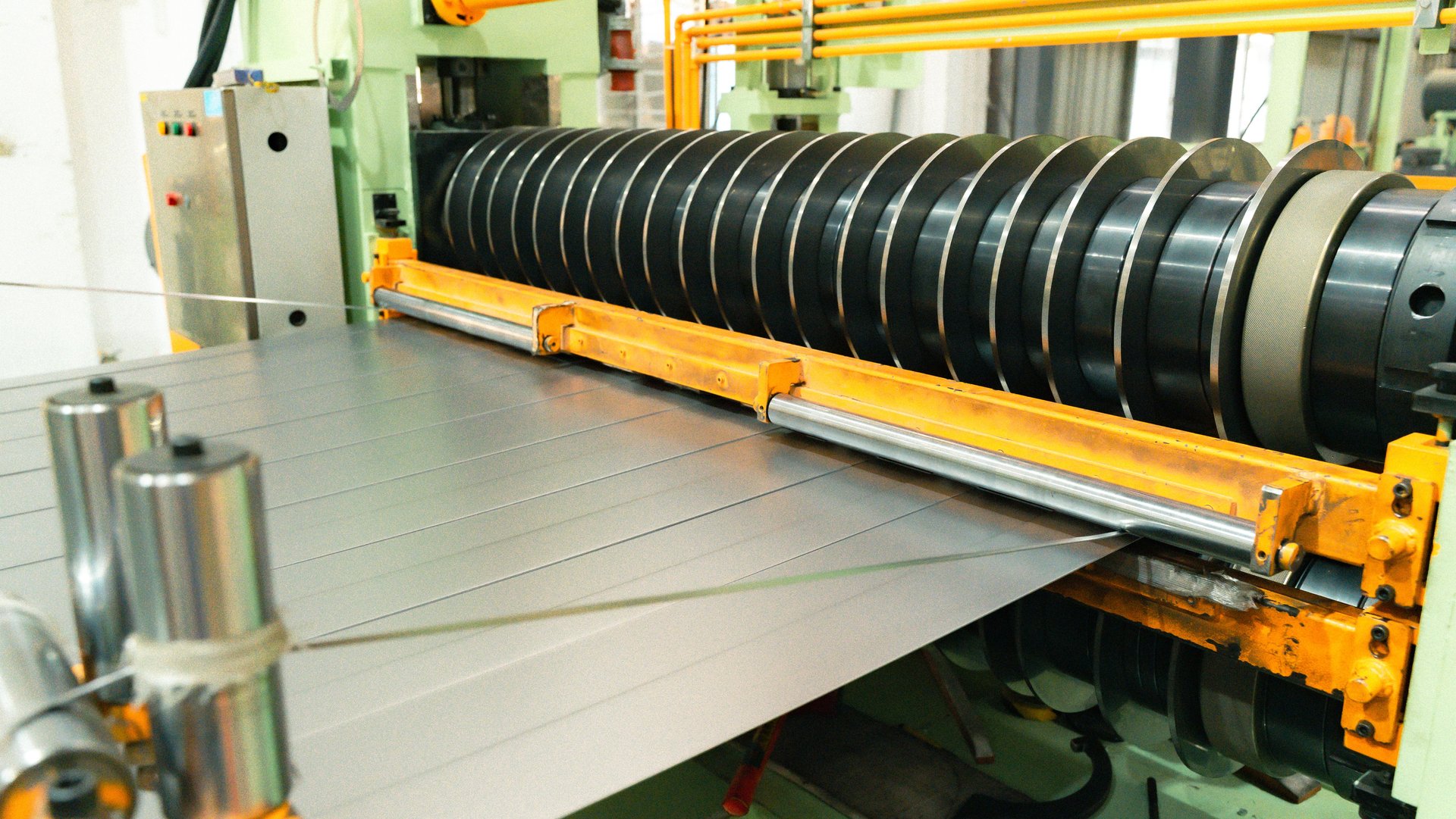
Side clearance is the horizontal relationship between the upper and lower circular knives. It allows the material to deform, penetrate and fracture between the cutting edges. Vertical overlap describes how far the cutting circles pass one another. The two settings interact, but they should not be treated as interchangeable corrections.
If side clearance is unsuitable for the actual material and thickness, the edge may show an excessive rollover, a wide burnished zone, irregular fracture, heavy burr or tearing. Too much or too little overlap can increase cutting force, accelerate tool wear or create unstable separation. The useful setting depends on the material’s mechanical properties, thickness, coating, tool geometry and required edge condition. A value that works for one steel should not become a universal rule for every coil.
The fracture faces on both sides provide evidence. Operators should compare the drive-side and operator-side edges, the upper and lower surfaces, and the first, middle and last strips across the width. If all strips show a similar defect, the cause may be a general setting or material issue. If only one position is affected, local tooling, spacer, shaft or alignment conditions deserve closer attention.
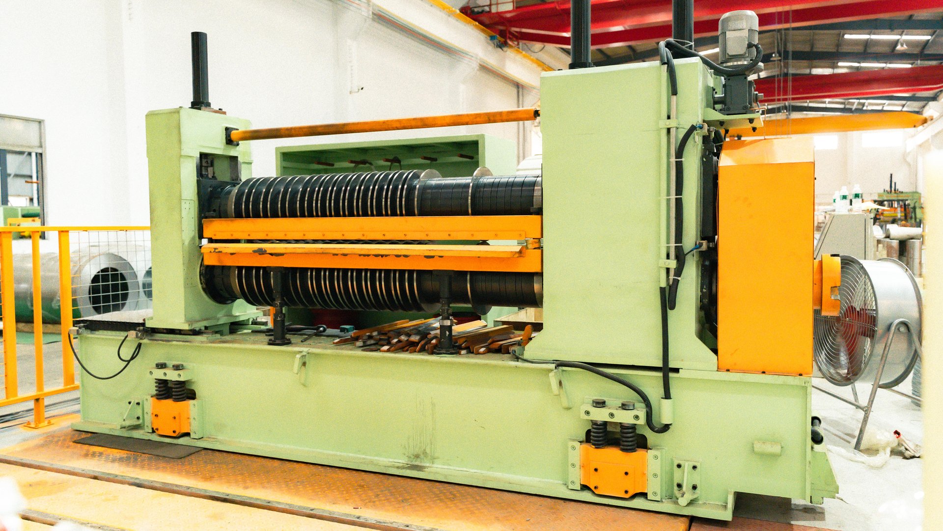
Tooling condition can imitate an incorrect setting
A correct nominal clearance cannot compensate for a damaged knife edge, contaminated spacer face or worn shaft support. Before assembling the stack, clean the knives, spacers, rubber rings, shaft shoulders and reference surfaces. Inspect for chips, scoring, corrosion, embedded debris and uneven wear. A small contaminant between spacers can accumulate into a meaningful positional error across a wide stack.
Knife runout and shaft runout affect the cutting relationship during rotation. Static spacing may appear correct while the real clearance changes once the tooling turns. Bearing condition, axial restraint and tightening sequence should be checked according to the machine and tooling procedure. If a burr appears periodically rather than continuously, compare its interval with knife rotation, shaft rotation or another repeating mechanical event.
Tooling records should identify which knives were used, their inspected condition, sharpening history and the spacer arrangement. Mixed tooling sets can introduce differences in diameter or thickness. Repeatable edge quality becomes difficult when components return from storage without identification or when the setup sheet does not match the physical stack.
Read the burr pattern before changing the machine
The first diagnostic step is to preserve the evidence. Mark strip number, edge, coil identity, material, thickness, line speed and sample position. Evaluate the edge using the agreed method. “The burr is high” is less useful than a mapped pattern showing where the defect occurs and whether it changes during the coil.
A defect on every corresponding upper-cut edge may point toward one relationship in the knife arrangement; a defect limited to one strip may indicate local wear or a spacer problem. A defect that worsens as speed changes may involve strip stability, vibration or dynamic tooling condition. A result that changes through the coil can also be related to material condition, strip tracking, coil shape or contamination rather than a fixed setting alone.
Do not adjust several variables at once. Record the baseline, change one verified factor, produce a controlled sample and compare the same edges. If clearance, overlap, guiding and tension are all changed together, the team cannot know which action helped or whether another quality characteristic deteriorated.
The existing guide to how a coil slitting line works is useful when tracing the defect beyond the knife stand. Upstream lateral movement can change the way material meets the knives, while downstream crossing or poor separation can damage an edge that was cut acceptably.
Strip guidance and separation protect the cut edge
Entry guides should establish a stable centerline without squeezing, marking or forcing the strip. If the material hunts laterally, the knife relationship cannot remain consistent. Check the master coil for telescoping or damaged edges, confirm the uncoiler and guide centerlines, and observe the strip at low speed before blaming the tooling.
After cutting, the strips require organized separation. Separator discs and contact rolls should correspond to the approved strip plan and remain clean. Adjacent strips that rub, overlap or cross can create secondary edge damage. Uneven tension can pull one strip differently from the others and make an otherwise acceptable edge appear unstable farther downstream.
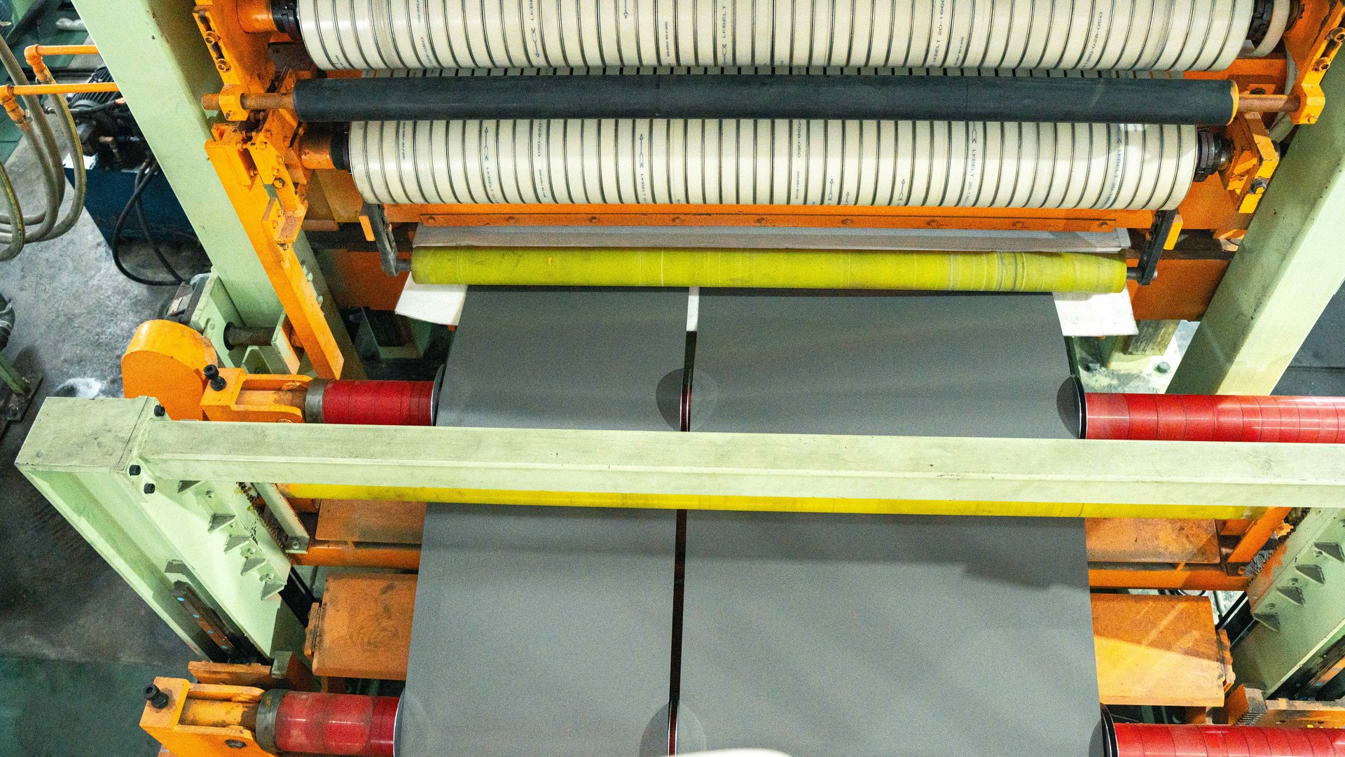
Surface-sensitive material adds another constraint. Tooling, guides and contact surfaces must be suitable for the product. A corrective action that reduces burr but introduces scratches, impressions or coating damage is not a complete solution. The final decision should consider edge, width, surface and winding together.
Build a controlled setup and maintenance record
A stable setup begins with confirmed material data and an approved strip plan. Assemble from a fixed reference, verify trim widths and total stack width, check upper/lower relationships, then inspect separator positions before threading. Run a low-speed trial, map the edges and confirm that scrap leaves the cutting area reliably. Production speed should be introduced only after the basic condition is stable.
Save the accepted arrangement with the material and quality result. Useful records include coil identity, thickness, material grade, knife and spacer set, clearance and overlap method, strip plan, line speed, burr result and any corrective action. Over time, these records reduce trial-and-error and help distinguish normal tooling wear from a new machine or material problem.
Lubrication and general inspection also influence repeatability. Contaminated or poorly maintained mechanisms can develop movement, heat or wear that changes the tooling relationship. The RONGXING articles on slitting-line lubrication and maintenance management provide supporting checks beyond the knife stack.
When requesting technical support, send the material specification, thickness, strip plan, photographs of both edges, measured pattern, tooling record and the operating condition. This evidence is more useful than a single burr value. For a project review or troubleshooting discussion, contact RONGXING with the complete cutting and inspection data.