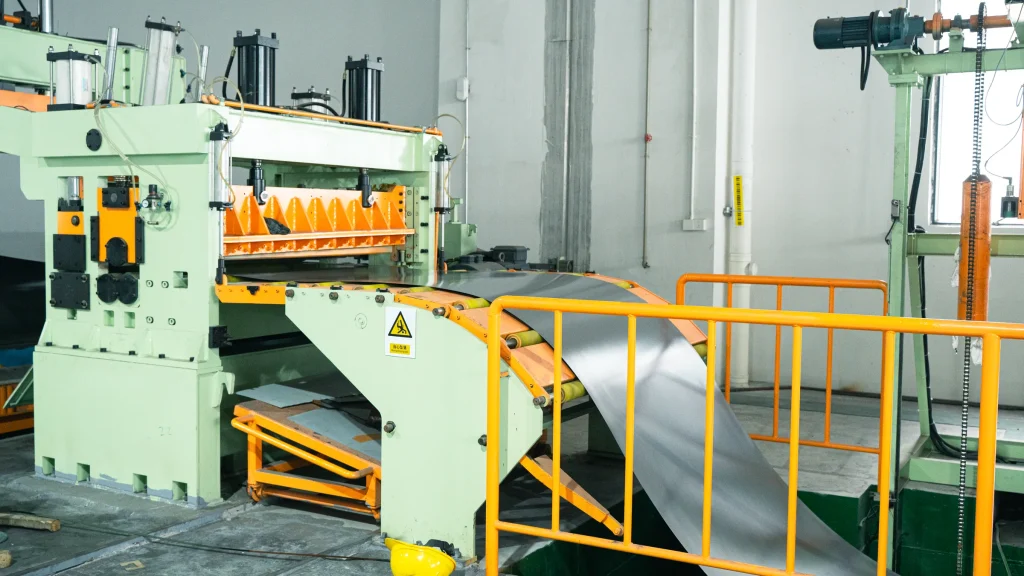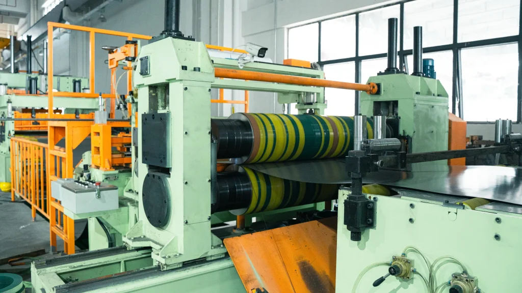
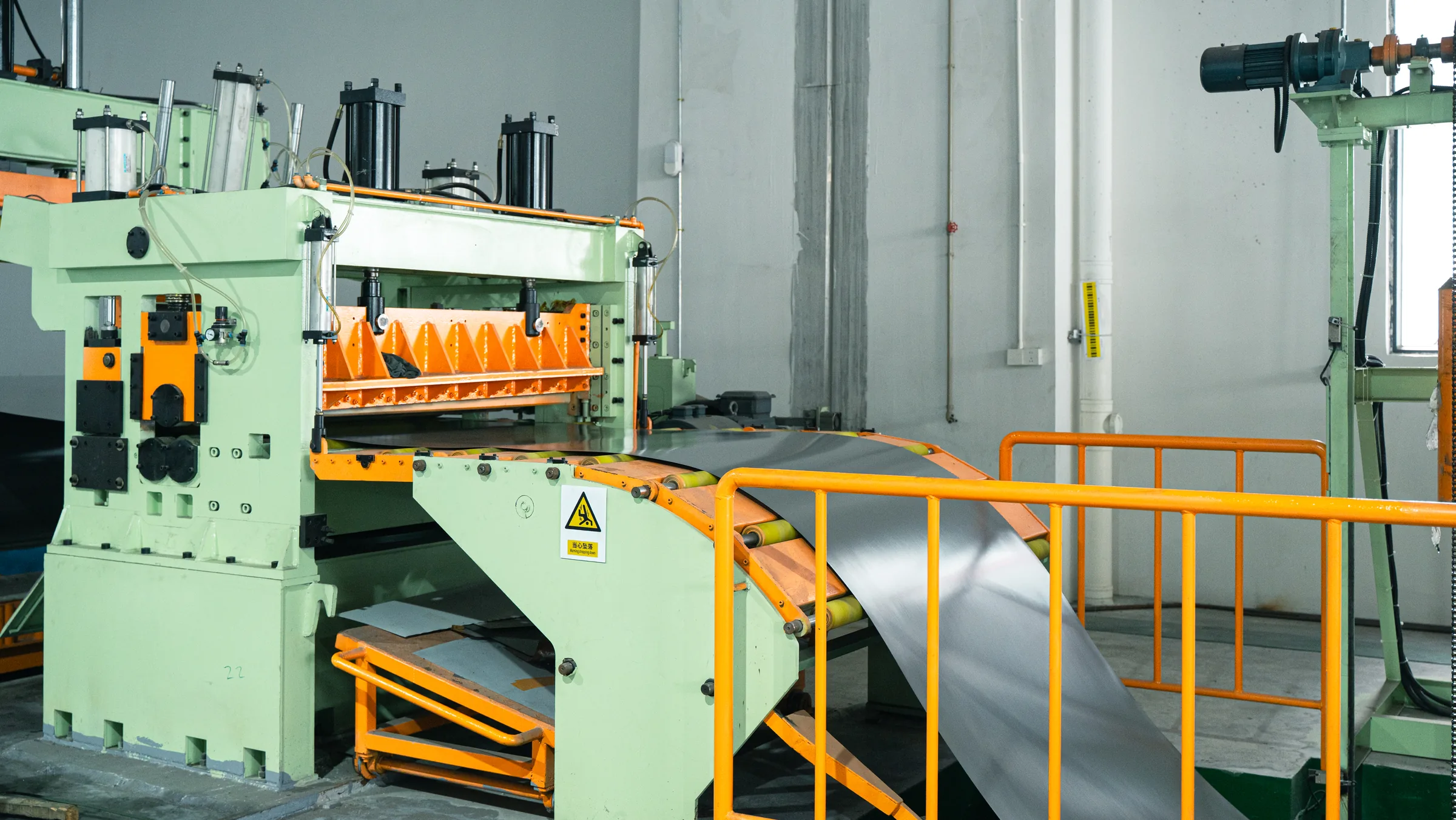
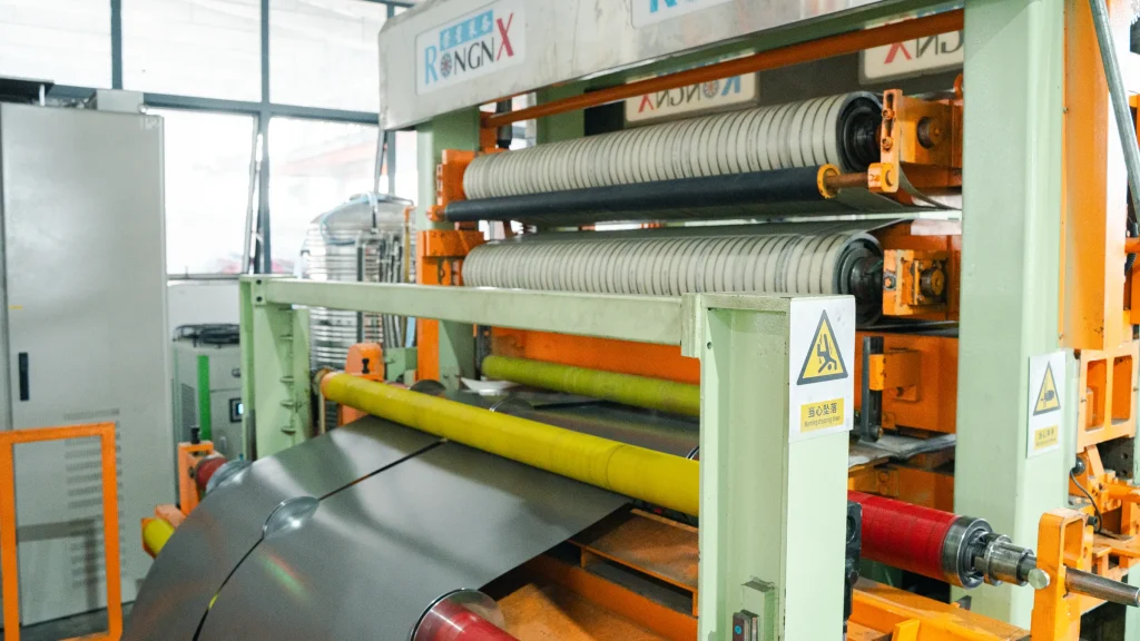
A coil slitting line divides a wide master coil into narrower strips and rewinds them under controlled tension. On the RONGXING 1650mm Coil Slitting Line, the exact drive and control configuration is selected from the material, thickness, width, slit pattern, coil size, and finished-coil requirement.
The original Chinese article explains the recoiling process through four connected calculations: constant-tension control, synchronous motor speed, minimum operating speed, and the relationship between strip tension and motor torque. Those four technical sections and their numerical examples are retained below.
The calculations are theoretical examples, not universal machine ratings. The original article also contains two formula or decimal inconsistencies; they are identified and corrected here so that the technical logic is preserved without publishing the wrong result.
1. Constant-tension control principle
The basis of constant-tension control during unwinding and rewinding is knowing how the coil diameter changes while the line is running. As the winding diameter changes, the motor torque must change with it if the strip is to remain under the required tension.
The original example uses a V-series variable-frequency drive with torque-control capability. It describes three analog input terminals—AUI, AVI, and ACI—that can be assigned different functions. One input can be selected as the torque reference and another as the speed limit. In that example, a 0–10 V signal corresponds to 0–100% of the motor’s rated torque, so changing the command voltage changes the torque reference used for tension control.
For a slitting line, coil diameter can be calculated by a dedicated tension controller or by a PLC-based control system. The required tension is entered through the HMI or text display, the control system calculates or tracks the winding diameter, and the required winding torque follows the basic relationship:
T_drum = F × D / 2 = F × r
where:
T_drum= torque at the winding drum, in N·m;F= strip tension, in N;D= current coil diameter, in m;r= current coil radius, in m.
The PLC or tension controller can then send the required torque reference to the drive. In the legacy example this is an analog output connected to the V-series drive’s torque-reference terminal. Other machines may use different drives, feedback devices, and digital communication, so this analog architecture should be treated as the original control example rather than as the only possible design.
This relationship explains why the drive command cannot remain fixed: if the required strip tension F remains constant while diameter D increases, the required drum torque increases proportionally. The recoiling system is only one part of the complete coil-processing equipment range, but its control must remain coordinated with the rest of the line.
2. Synchronous speed calculation
The original article next considers the low-frequency operation of an AC induction motor. In the drive system used for the example, low-frequency motor performance is described as less stable, with reduced excitation torque and poorer linearity. The design therefore tries to avoid operating the recoiler motor below 2 Hz during the winding process.
For a four-pole motor, synchronous speed can be written as either:
n_s = 120 × f / P
or:
n_s = 60 × f / p
where:
f= supply frequency, in Hz;P= total number of motor poles;p= number of pole pairs;n_s= synchronous speed, in r/min.
For a four-pole motor, P = 4 and p = 2. At the rated frequency of 50 Hz:
n_s = 120 × 50 / 4 = 1,500 r/min
At the 2 Hz lower-frequency reference used in the original article:
N = 1,500 × 2 / 50 = 60 r/min
This preserves the original result of 60 r/min while correcting its ambiguous printed formula. An induction motor’s actual shaft speed is normally slightly below synchronous speed because of slip, so final drive calculations should use the motor and inverter data for the real machine. If low-speed behavior or production settings need to be checked on installed equipment, the machine-specific route is RONGXING service and support, not a universal frequency assumption.
3. Speed-limited operation
Once the 60 r/min lower motor-speed reference has been established, the original article calculates the corresponding minimum line speed at the maximum winding diameter:
V = π × D × n / i
Using the original values:
- maximum winding diameter
D = 1.2 m; - minimum motor speed
n = 60 r/min; - reduction ratio
i = 9;
the result is:
V_min = 3.14 × 1.2 × 60 / 9 = 25.12 m/min
In this example, approximately 25.12 m/min is the line speed associated with a 1.2 m coil diameter when the motor is operating at 60 r/min through a 9:1 reduction ratio. Running more slowly under the same assumptions would require the motor frequency to fall below the original 2 Hz reference.
The article also states that speed must be limited during tension-control operation to prevent an uncontrolled acceleration or “runaway” condition. In practice, torque control, speed limiting, line coordination, braking, feedback, and safety logic must be reviewed together for the installed drive system. Related working-principle material can be distributed through the RONGXING coil-processing guides without replacing the machine manual or commissioning parameters.
4. Tension and torque calculation
The final part of the original article calculates the maximum theoretical strip tension from motor torque and the gearbox ratio. To keep the notation consistent, let T_motor be the motor-shaft torque. Ignoring drivetrain losses, the relationship is:
F × D / 2 = T_motor × i
Therefore:
F = 2 × T_motor × i / D
where:
F= strip tension, in N;D= winding diameter, in m;T_motor= motor rated torque, in N·m;i= reduction ratio.
Motor rated torque can be estimated from power and rated speed:
T_motor = 9550 × P / n
where:
P= motor power, in kW;n= motor rated speed, in r/min.
For the original 3.7 kW motor example, a torque of 24.88 N·m corresponds to a rated speed of approximately 1,420 r/min:
T_motor = 9550 × 3.7 / 1420 ≈ 24.88 N·m
Using the original reduction ratio i = 9 and winding diameter D = 0.6 m:
F_max = 2 × 24.88 × 9 / 0.6 = 746.4 N
The old Chinese article prints 74.64 N, but the arithmetic from its own formula and values gives 746.4 N. The corrected theoretical result is therefore 746.4 N before mechanical efficiency, control margin, material limitations, and other real-system losses are considered.
If gearbox and drivetrain efficiency η are included, a more practical simplified expression is:
F ≈ 2 × T_motor × i × η / D
These equations show the original engineering logic: coil diameter, motor speed, motor torque, gearbox ratio, and tension are connected. They do not by themselves determine a safe production setting or a complete machine specification.
To discuss a real configuration, send the material, thickness, width, slit pattern, coil dimensions, target speed, and recoiling requirements through the RONGXING Contact page. The engineering team can then replace the example assumptions with project-specific values.
FAQ
Why must recoiler torque change as coil diameter increases?
Because T_drum = F × D / 2. If strip tension remains constant, the required drum torque increases as the winding diameter increases.
What does the 0–10 V signal represent in the original example?
It is the analog torque-reference signal for the cited V-series drive, with 0–10 V mapped to 0–100% of rated motor torque. Other systems may use different signals.
Why does the original calculation use 2 Hz?
The original drive example treats 2 Hz as its preferred lower operating reference because very-low-frequency induction-motor performance may be unsuitable. It is not a universal limit.
How is the 25.12 m/min value calculated?
It uses V = π × D × n / i with D = 1.2 m, n = 60 r/min, and i = 9, giving approximately 25.12 m/min.
Is the calculated maximum tension 74.64 N or 746.4 N?
Using the original equation and inputs gives 746.4 N. The 74.64 N value in the old article is a decimal-place error.
Can these example values be used directly to order or operate a slitting line?
No. Actual settings depend on the motor, drive, ratio, efficiency, coil diameter, material, strip dimensions, tensioning system, and machine limits.