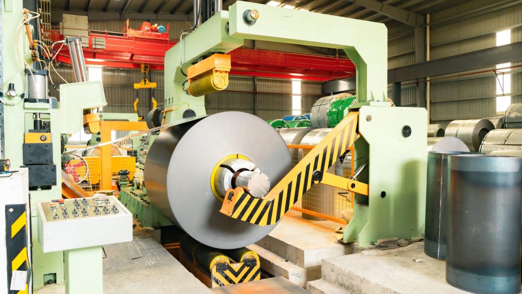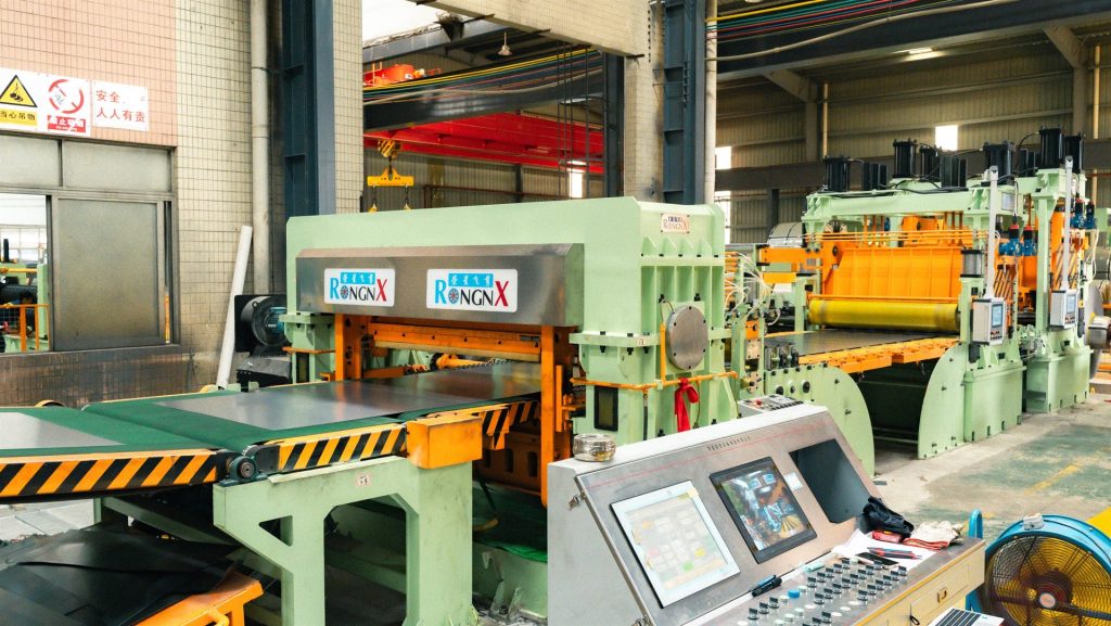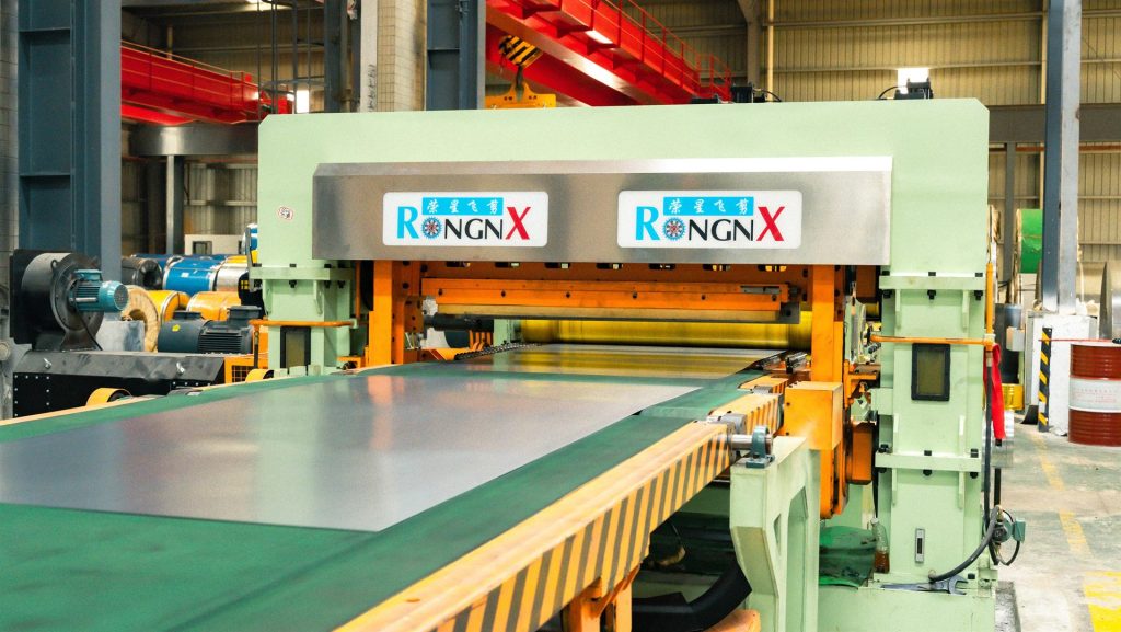
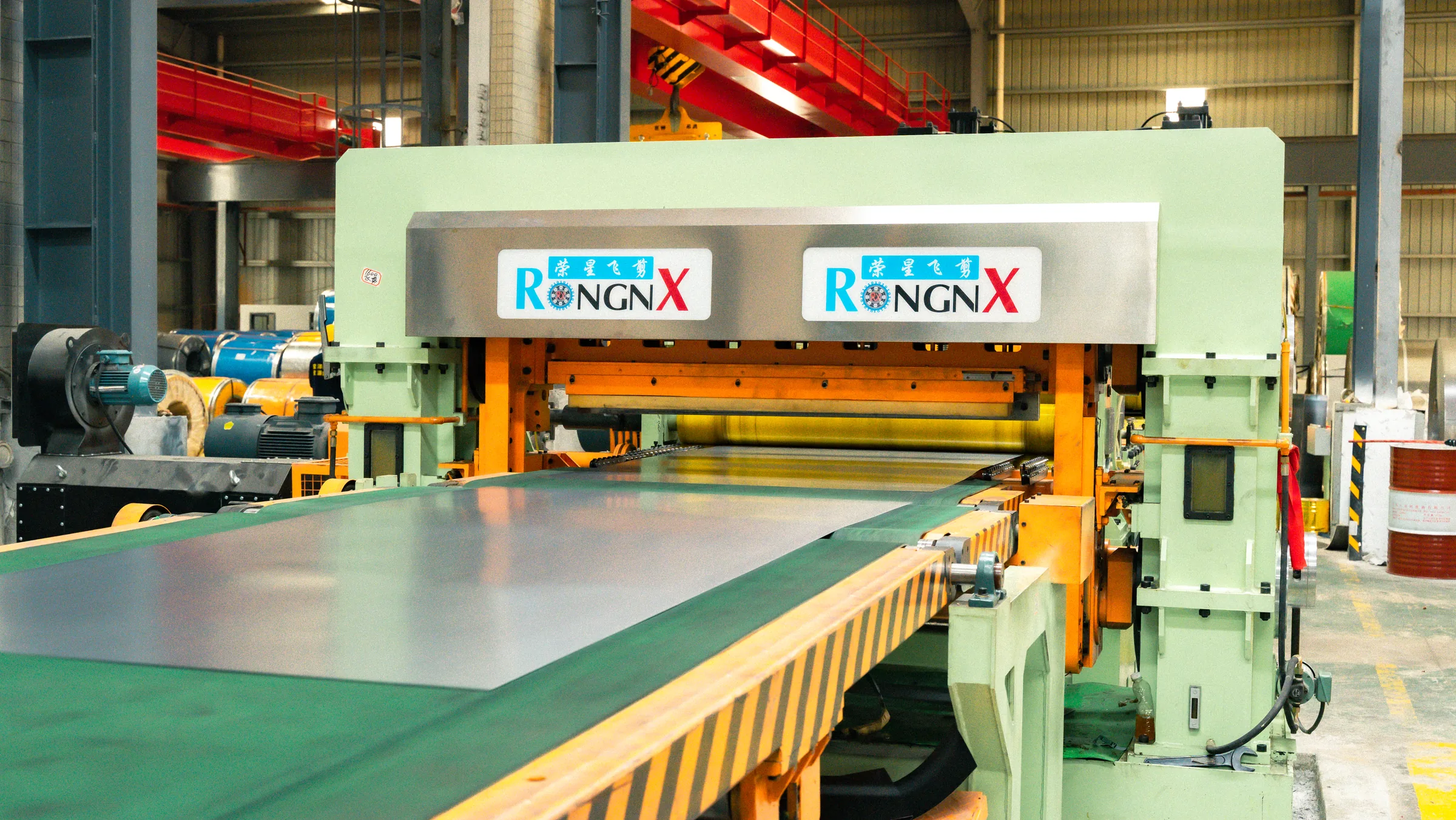
Cut-length accuracy is not created by one encoder, one servo, or one controller. It comes from a complete chain: the strip must travel predictably, the measuring device must represent that travel, the control system must calculate the cutting point, the shear must complete the motion at the correct time, and the finished sheet must be measured under an agreed method.
Review the complete Flying Shear Cut-to-Length Lines range to place synchronization, measurement and cutting accuracy in the context of the full production process.
When an error appears, replacing or adjusting one component without checking the full chain can hide the real cause. A useful diagnosis begins by identifying whether the error is consistent, changes with speed, changes with sheet length, appears only on certain materials, or begins after mechanical or tooling work.
From strip travel to the finished cut
The measuring section tracks strip movement as material travels through the line. Depending on the machine configuration, feedback may come from a measuring roll and encoder, a driven section, or another verified measuring arrangement. The important point is that the signal must represent actual strip travel closely enough for the production requirement.
The controller uses this feedback together with the target sheet length and current line condition. It determines when the cutting sequence needs to begin rather than simply waiting until the measured value equals the final length. The cutting mechanism needs time to accelerate, synchronize, complete the cut, and prepare for the next cycle.
In a Flying Shear line, the strip normally continues moving during the cut. The shear motion must reach the required relationship with strip speed and position during the cutting window. If the mechanical design uses a travelling carriage or another synchronized moving arrangement, its actual sequence should be explained for that machine rather than described with a generic animation.
The blade then passes through the material and separates the sheet. The physical cut still depends on blade clearance, overlap, sharpness, alignment, frame condition, material strength, and strip support. Correct electronic timing cannot compensate for every mechanical or tooling problem.
After the cut, the sheet moves onto the conveyor. Separation, support, braking, and stacking can influence how the sheet sits when it is measured. A sheet that is bowed, skewed, damaged, or not fully supported may produce inconsistent inspection results even when the cutting point is repeatable.
This is why cut length should be treated as a process result. Measurement, feed stability, synchronization, mechanical response, cutting, and inspection all contribute:
strip travel → measurement feedback → cut calculation → shear motion → blade contact → sheet handling → inspection
The chain also explains why the same setting can behave differently with another material. Surface, thickness, strength, coil condition, strip tension, and leveling response can change the way the strip contacts rolls and moves through the line.
Where length variation can enter the process
Slip at the measuring point is one possible source. If a measuring roll does not maintain stable contact, its rotation may not represent the strip accurately. Surface condition, oil, contamination, pressure, roll wear, vibration, acceleration, and tension can all affect contact. The remedy depends on the cause; simply changing a correction value may move the error without making the process stable.
Feed instability can create a similar result. Sudden tension changes, poor coil control, guiding problems, unstable looping, or inconsistent drive response can change strip movement around the measuring section. The line should be observed as a complete material path, not only at the encoder.
Mechanical condition matters between the command and the cut. Backlash, worn bearings, loose couplings, drive-train play, carriage condition, frame alignment, and inconsistent motion can affect repeatability. If the error changes direction, appears after reversal, or grows during operation, mechanical inspection may be as important as control tuning.
Synchronization error can appear when the measured strip position and the actual cutting motion do not reach the intended relationship. The cause may involve timing, speed feedback, acceleration, motion response, parameter setup, or a mechanical delay. The diagnosis should compare commanded and actual behavior using the tools available on the verified control system.
Blade and tooling condition can affect the observed sheet length and edge. Incorrect clearance, dull blades, poor alignment, material movement during penetration, or deformation near the cut may change where inspectors believe the finished edge begins. Length, burr, edge shape, and squareness should therefore be checked together when the problem appears around the cut.
Material and sheet geometry can affect inspection. A sheet with coil set, poor flatness, camber, or diagonal error may give different results depending on where and how it is measured. Measuring along one edge does not fully describe a sheet whose ends are not square. The inspection plan should identify the reference edge, measuring points, tools, support surface, and temperature or settling condition where relevant.
The pattern of the error provides useful clues. A nearly constant offset may point toward setup, reference, compensation, or a consistent mechanical delay. Variation that grows with sheet length may suggest a measuring-scale or slip relationship. Error that changes with speed may involve contact, tension, response, or synchronization. Random variation may require checking material travel, mechanical condition, signal stability, blade condition, and inspection method.
These are diagnostic directions, not automatic conclusions. The same pattern can have more than one cause, and adjustments should be made only after the production condition is recorded.
Define accuracy before trying to prove it
An accuracy statement needs a test condition. The buyer and supplier should agree on material grade, thickness, width, coil condition, sheet length, line speed or production mode, number of sheets, warm-up state, and measuring method. Without those conditions, the same accuracy number can describe very different tests.
The sample plan should show whether every sheet is measured or whether selected sheets are checked from the beginning, middle, and end of a run. It should also define how results are recorded. Average error alone can hide variation, while one unusual sheet should not be used to describe a stable run without investigation.
Check more than one sheet length when the production program requires it. A correction that works at one length may not show whether the measurement scale remains consistent over another length. If speed changes with the program, the test should identify that as well.
Use a suitable measuring tool on a stable surface. Confirm the reference points and do not mix readings from different edges or methods. For long or flexible sheets, support and alignment are important. If diagonal or squareness is required, include it as a separate recorded result rather than assuming correct length proves correct geometry.
The acceptance plan should distinguish machine repeatability from incoming-material effects. If a sample coil has severe shape or surface problems, those conditions need to be documented. If the contract requires a particular production material, the buyer and supplier should agree who provides it and how much is needed for the test.
Avoid adjusting the machine after every single sheet. First collect enough results to identify a pattern. Record the recipe, material, sheet length, speed, measured values, blade condition, and relevant alarms or operator actions. Controlled changes make it possible to learn which factor affected the result.
The same discipline should continue after installation. Keep a simple baseline from the accepted setup, then compare later results after a blade change, maintenance work, new material, or parameter change. This makes troubleshooting faster than relying on memory.
A practical check when cut length changes
Begin with the production facts:
- Which material, thickness, width, and coil were running?
- Which sheet length, line condition, and recipe were selected?
- Is the error constant, proportional, speed-related, or random?
- Does it occur on both sheet edges and does diagonal remain acceptable?
- Did it begin after a blade change, maintenance action, material change, alarm, or parameter edit?
Then check the process in order. Confirm the inspection method and measuring tool first. Inspect the finished edge and sheet geometry. Observe strip travel, guiding, tension, and measuring-roll contact. Review the measuring signal and recipe. Check the shear motion and mechanical condition. Inspect blade clearance, alignment, and wear. Make one controlled correction at a time and repeat the agreed sample test.
Do not use compensation to cover an unstable process. A correction value can be useful when the process is repeatable and the relationship is understood. If readings scatter because the strip slips, the motion is inconsistent, or the inspection method changes, compensation alone will not create stable production.
Does a higher-resolution encoder automatically improve cut accuracy? No. Resolution is only one part of the system. Strip contact, feed stability, signal use, motion response, mechanics, tooling, and the inspection method still affect the finished result.
Why can cut length change when line speed changes? Speed can change strip contact, tension, acceleration, motion response, synchronization, conveyor behavior, and the timing available for the cutting cycle. The actual cause needs to be measured on the specific line.
Can the operator correct a constant length offset? A controlled correction may be appropriate after the measuring method and process stability are confirmed. The cause and allowed adjustment procedure should be documented for the machine.
Why should diagonal be checked together with length? A sheet can measure correctly along one edge while the cut is not square. Length and diagonal describe different parts of the finished geometry.
Does blade wear affect length measurement? Blade wear does not change the measuring signal directly, but it can affect edge shape, deformation, cut behavior, and the point used during inspection. Tooling and measurement should be reviewed together.
What information helps remote or on-site diagnosis? Provide material data, recipe and sheet length, speed or production mode, a sequence of measured results, photos of the cut edge, blade and maintenance history, alarm records, and a clear description of when the problem began.
You can review the RONGXING Flying Shear Cut-to-Length Line family or send the material, production setting, measurement record, and cut samples through the Contact page. The next step should be based on the observed error pattern rather than a guessed component replacement.
FAQ
Does a higher-resolution encoder automatically improve cut accuracy?
No. Resolution is only one part of the system. Strip contact, feed stability, signal use, motion response, mechanics, tooling, and the inspection method still affect the finished result.
Why can cut length change when line speed changes?
Speed can change strip contact, tension, acceleration, motion response, synchronization, conveyor behavior, and the timing available for the cutting cycle. The actual cause must be measured on the specific line.
Can the operator correct a constant length offset?
A controlled correction may be appropriate after the measuring method and process stability are confirmed. The cause and allowed adjustment procedure should be documented for the machine.
Why should diagonal be checked together with length?
A sheet can measure correctly along one edge while the cut is not square. Length and diagonal describe different parts of the finished geometry.
Does blade wear affect length measurement?
Blade wear does not change the measuring signal directly, but it can affect edge shape, deformation, cut behavior, and the point used during inspection.
What information helps remote or on-site diagnosis?
Provide material data, recipe and sheet length, speed or production mode, measured results, cut-edge photos, blade and maintenance history, alarm records, and when the problem began.