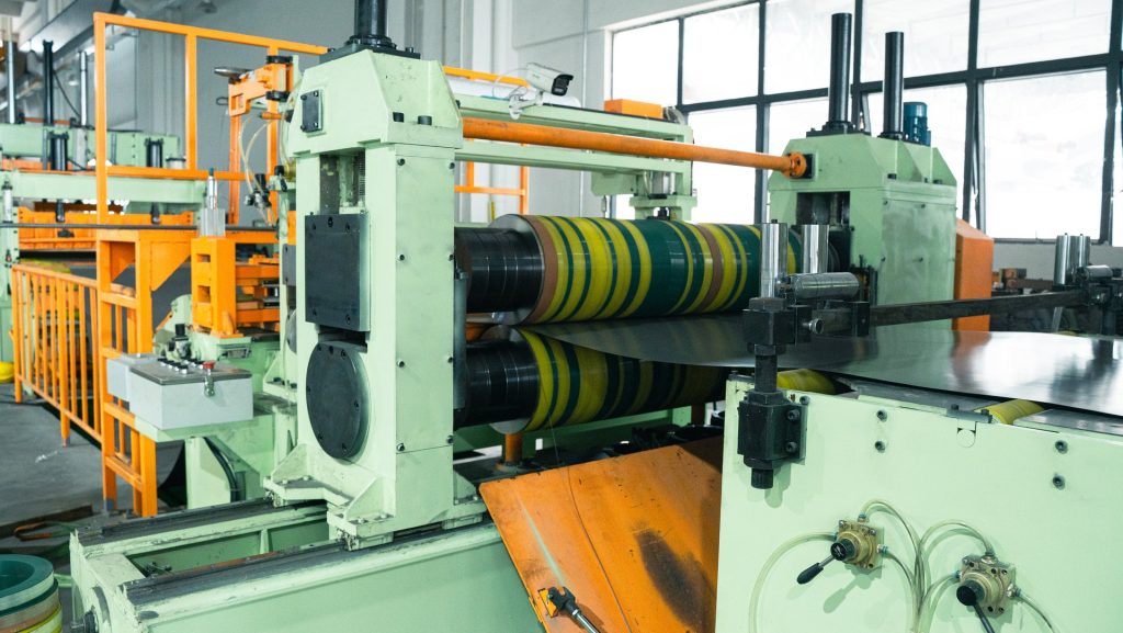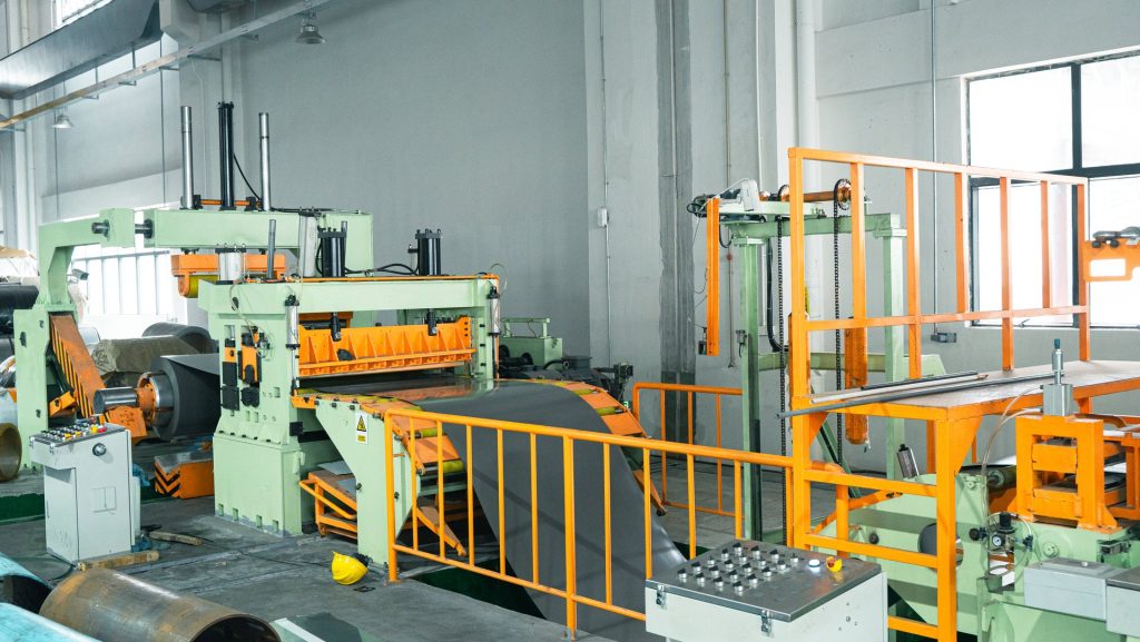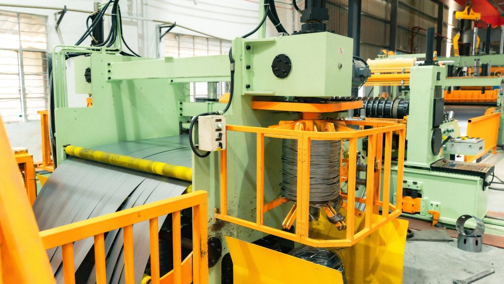
Recoiling is where every upstream condition becomes visible in the finished product. A coil may leave the knife stand with acceptable strip width and edge quality, yet arrive at unloading with loose wraps, offset layers, telescoping or uneven edges. These winding defects are often blamed on the recoiler alone, but the actual cause may begin with strip separation, tension distribution, line alignment, tooling or master-coil condition.
In a complete coil slitting line, multiple narrow strips must travel different positions across the machine while remaining organized and controlled. The diagnostic task is to identify whether the defect affects every strip, one strip, one side of the recoiler or a specific period of the coil. That pattern determines where the investigation should begin.
The finished coil reveals the tension history
Stable winding requires enough controlled tension to build compact, aligned layers without damaging or permanently stretching the material. Too little tension can allow loose wraps and lateral movement. Excessive or uneven tension can mark sensitive surfaces, distort thin strip or cause different strips to build under different conditions. The useful operating window depends on material, thickness, strip width, surface, coil diameter and downstream handling requirement.
Telescoping describes layers shifting axially so the coil sides no longer remain in one plane. It can develop progressively, appear suddenly after a speed or tension change, or affect only selected strips. A uniformly loose group of coils suggests a different cause from one narrow strip that repeatedly walks to the side. The operator should preserve that distinction before changing a general tension value.
Record the master-coil identity, strip plan, strip positions, line speed, recoiler diameter and the point at which the pattern appears. Photograph both coil faces and mark the corresponding strip positions. If possible, compare the winding condition at several diameters rather than inspecting only after unloading.
Unequal strip behavior can begin upstream
After slitting, strips may not behave identically. Differences in strip width, material profile, camber, edge condition or path length can affect how they travel through the tension and separation sections. If strips cross, rub or enter at different angles, the recoiler receives an unstable bundle even when its own control is functioning correctly.
Check separator-disc positions against the actual strip plan. Discs should keep the strips organized without damaging the edges or surfaces. Contact rolls and tension surfaces should be clean, correctly aligned and suitable for the material. Wear, contamination or uneven loading can create different resistance across the width.
The master coil also matters. Telescoping, damaged edges or unstable payoff can introduce lateral movement at the entry. Guide corrections farther downstream may temporarily hide that movement without removing it. Observe the entire strip path at a controlled speed and identify where the first lateral displacement begins.
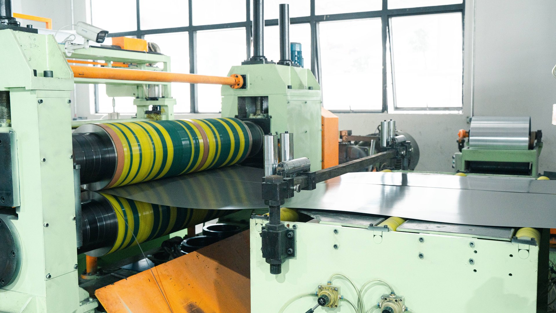
The process explanation in How Does a Coil Slitting Line Work? can help teams trace a winding problem from payoff through cutting, separation and recoiling rather than isolating only the final machine section.
Inspect the recoiler as a mechanical and control system
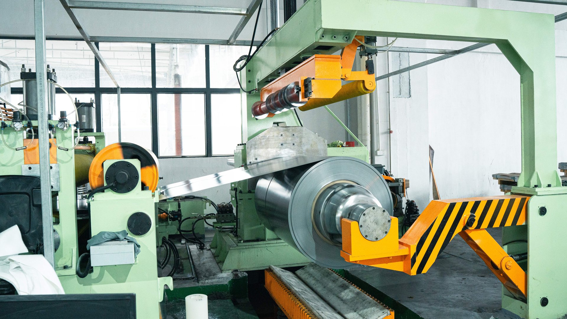
At the recoiler, confirm the mandrel condition, expansion, support, alignment and core or drum arrangement. The finished-coil inner diameter and required unloading method must match the selected setup. A worn support, incomplete expansion or poor core condition can allow movement that becomes more visible as coil weight increases.
Check the relationship among recoiler centerline, separator section and incoming strip path. A lateral offset can pull the group toward one side. If the defect changes with coil diameter, inspect the mechanical support and the way torque or tension is controlled during buildup. Abrupt changes in acceleration, deceleration or recipe state can leave a visible band in the finished coil.
Control data should be evaluated together with the physical result. Compare commanded and actual drive status, tension-related signals, speed transitions, alarms and operator adjustments at the time the defect appeared. A stable displayed value does not prove that every strip experienced the same tension, so the winding pattern and material path remain essential evidence.
Do not correct a lateral alignment problem by applying excessive general tension. The coil may appear tighter while edge loading, strip distortion or surface marking becomes worse. Similarly, software compensation should not be used to hide looseness caused by a mechanical support or separator problem.
Diagnose by pattern instead of by guesswork
A practical investigation can begin with four questions. Does the defect affect all strips or selected strips? Is it present from the first wraps or only after diameter increases? Does it change with speed or acceleration? Does the direction correspond to a line-center or alignment condition?
If all finished coils are loose, inspect the general tension method, drive response and recipe. If one strip is loose, check its width, path, separator position, contact condition and material profile. If several adjacent strips move together, inspect the local section of the separator or tension device. If the problem occurs at a repeatable diameter, compare the event with recipe transitions, drive behavior and mechanical loading.
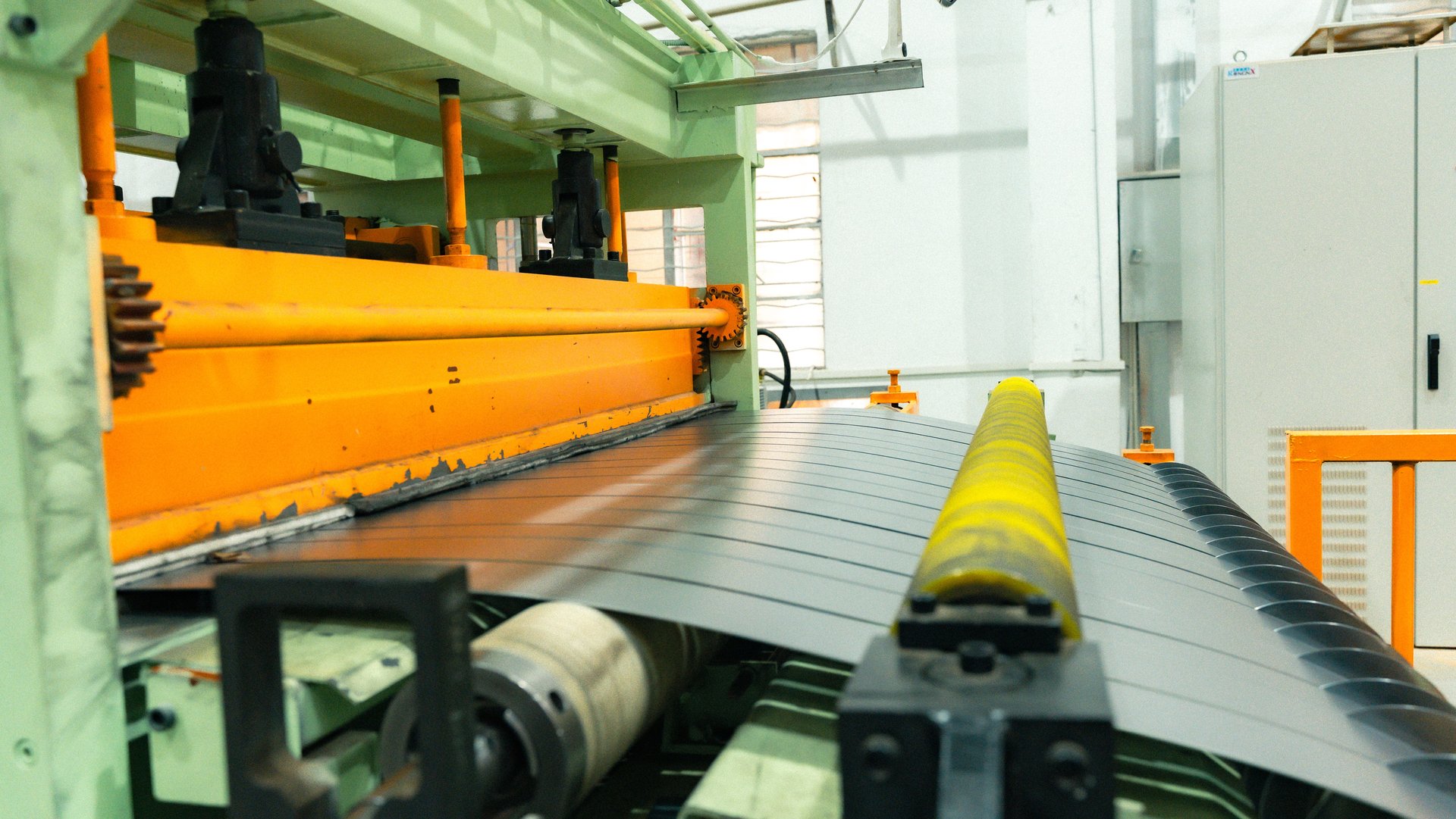
Change one verified cause at a time. Reproduce the same strip plan and sample condition, then compare the coil faces, tightness and layer alignment. A correction should be accepted only if it improves winding without worsening width, burr, camber or surface quality.
Define winding quality before the production test
The technical agreement should state what a usable finished coil means for the buyer. Relevant items can include inner and outer diameter, coil weight, face alignment, acceptable telescoping, winding tightness, edge protection, separator marks and unloading method. The parties should also agree on how the coil will be inspected and whether evaluation occurs on the machine, after unloading or before the next process.
Representative testing matters. One wide strip does not prove performance with many narrow strips, and an easy material does not prove every planned product. The factory test should include a meaningful strip arrangement and enough running condition to observe tension and coil buildup. Results and accepted settings should be recorded for future setup.
Maintenance protects that baseline. Separator components, contact surfaces, bearings, mandrel mechanisms, drive couplings and sensors should be inspected on a controlled schedule. The RONGXING guide to coil slitting line maintenance explains why records and preventive checks are more reliable than waiting for a rejected coil.
When external support is required, provide the strip plan, material data, coil-face photographs, operating speed, diameter at the first visible defect, alarm history and recent maintenance changes. RONGXING’s service scope can support the discussion, or buyers can submit the production data for review. A clear pattern is the fastest starting point for separating tension, alignment, mechanical and material causes.