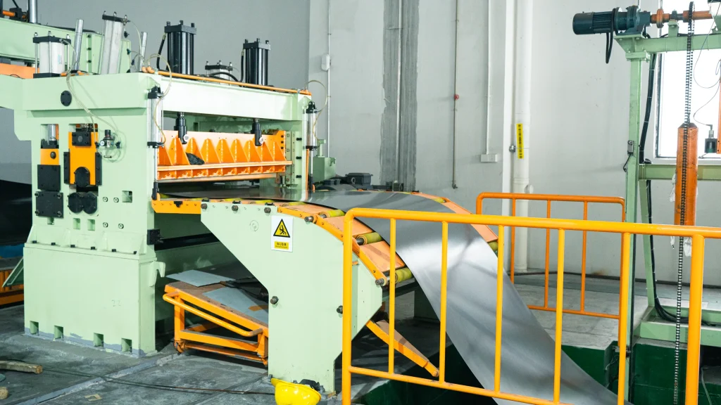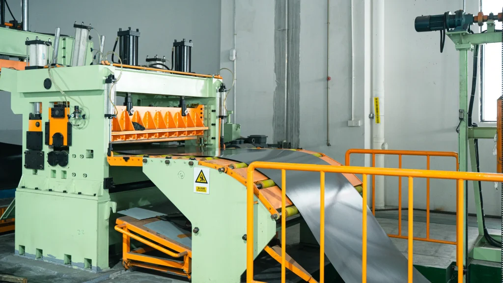
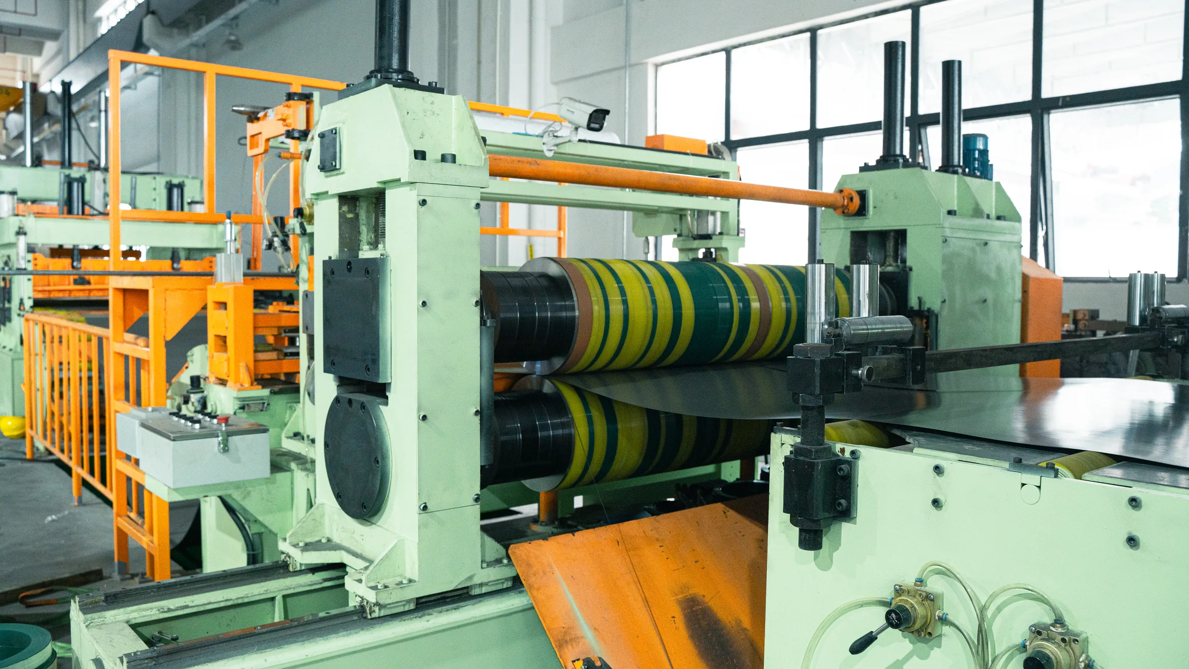
Material utilization describes how much incoming coil, strip, or sheet becomes the intended product. When production begins with a master coil, the width plan and feeding method should be considered together with the capability of the RONGXING 1650mm Coil Slitting Line.
The original Chinese article is titled “How to Improve Slitting Machine Utilization,” but its calculations concern material utilization for circular blanks arranged on strip material. This English version keeps that original example instead of replacing it with a different slitting-efficiency article.
The source evaluates utilization at three levels: one feed pitch, the complete strip, and the full parent sheet or coil. It then explains how transverse and longitudinal cutting depend on the feeding direction.
1. Material utilization for one feed pitch
For a continuous or progressive die, material utilization begins with the arrangement of circular blanks on the coil or strip. Two adjacent circles require a bridge or web of material between them. One feed pitch is the center-to-center distance from one circle to the next.
Within one pitch, the product area can be viewed as two half-circles—one half from each adjacent pitch—which together equal the area of one complete circle. The remaining bridge and surrounding strip area are scrap.
The step-pitch material utilization can therefore be expressed as:
η_pitch = area of one circular blank / material area used by one feed pitch × 100%
If the circle diameter is d, its area is:
A_circle = π × d² / 4
The material area for one pitch depends on the strip width and the feed pitch selected by the nesting layout. A smaller bridge can improve the calculated ratio, but the allowable bridge must still satisfy the die, material, feeding stability, and product-quality requirements.
This first calculation evaluates the repeating pattern only. It does not include the extra material at the beginning or end of the strip. The same distinction is useful when comparing layouts that may be processed on different types of coil-processing equipment.
2. Material utilization for the complete strip
Strip utilization goes one step further. In addition to the bridge scrap between two adjacent circles, it includes the material between the strip head and the first circle, as well as the material between the last circle and the strip tail.
The original article notes that the head and tail losses can be larger than the bridge loss between two circles. For this reason, a calculation based only on one repeating pitch may overstate the utilization of a short strip or a small production batch.
The complete-strip utilization is:
η_strip = total area of all circular blanks / total area of the strip × 100%
The same ratio can be calculated by weight when the material thickness and density are consistent:
η_strip = total weight of all acceptable blanks / total strip weight × 100%
This calculation includes every circle on the strip and the full strip length consumed, including the head and tail. When feed length, starting position, or strip layout is changed, the utilization should be recalculated for the complete strip rather than estimated from one pitch alone.
Production teams should also confirm that the theoretical layout can be fed and processed consistently. If setup or feeding behavior creates repeated head, tail, or positioning loss, it can be reviewed through RONGXING service and support using the actual material and process sequence.
3. Material utilization for the parent sheet or coil
The next level is the utilization of the large parent sheet or master coil from which several strips are cut. Depending on the selected parent width, there may be little width scrap or a large residual strip.
The original example uses a 1,000 mm-wide parent material. If the required strip width is 500 mm, two 500 mm strips fit exactly across the width:
1,000 mm = 2 × 500 mm
If the required strip width is 980 mm, only one 980 mm strip fits into the same 1,000 mm width, leaving the remaining width as residual or scrap. For that 980 mm strip, a 1,960 mm-wide parent material would theoretically allow two strips without width loss:
1,960 mm = 2 × 980 mm
However, the original article also points out that the ideal 1,960 mm specification may not be available. Material utilization therefore depends not only on arithmetic but also on which plate or coil widths can actually be purchased.
The article gives two ways to understand parent-material utilization. The first considers only the strips cut from the sheet or coil:
η_parent-strip = total area of all strips / total area of the parent sheet or coil × 100%
The second considers the final circular products relative to the complete parent material:
η_parent-product = total area of all circular blanks / total area of the parent sheet or coil × 100%
In everyday production discussions, “material utilization” often refers to the second definition because it includes all material consumed before the finished circular blanks are produced. That means the calculation must include parent-width residual, coil head and tail loss, strip head and tail loss, and the bridge scrap between adjacent circles.
The processing route changes the result. The original article gives three examples:
- Uncoil the material, cut rectangular sheets, shear those sheets into strips, and then punch the circles.
- Purchase rectangular material, cut it into strips, and then punch the circles.
- Feed coil strip directly into a continuous die and punch the circles in line.
Each route consumes and defines material differently, so each produces a different utilization result. More examples of how process sequence affects equipment and material decisions can be organized through the RONGXING coil-processing guides.
4. Transverse and longitudinal cutting direction
The original article concludes by defining transverse and longitudinal cutting according to the feeding direction.
During uncoiling, transverse cutting is perpendicular to the direction in which the strip travels. Longitudinal cutting is parallel to the uncoiling direction and is the direction associated with a slitting mechanism.
The same principle applies when a sheet is fed into a shearing process. For a rectangular blank, feeding along the long side and feeding along the short side create different reference directions. A cut described as transverse in one feeding arrangement may not be described the same way after the material orientation changes.
The production document should therefore define the feeding direction before using “transverse” or “longitudinal.” This prevents layout, width, length, and utilization calculations from being interpreted from different orientations.
To review a real width plan, send the available master-coil widths, required strip widths, downstream blank dimensions, feeding direction, and production route through the RONGXING Contact page.
FAQ
What is step-pitch material utilization?
It is the area of one repeated product—in the original example, one circular blank—divided by the strip area consumed by one feed pitch.
Why are two half-circles treated as one circle?
One pitch can be bounded by the centerlines of adjacent circles. The two half-circles inside those boundaries equal one complete product area.
Why is complete-strip utilization lower than pitch utilization?
The complete-strip calculation also includes the unused material before the first product and after the last product.
Why do 980 mm strips reduce utilization on 1,000 mm material?
Only one 980 mm strip fits across the 1,000 mm width, leaving 20 mm. A 1,960 mm parent width would fit two 980 mm strips theoretically, but that width may not be available.
Which definition of material utilization should be used?
State whether the ratio measures strips relative to the parent material or final products relative to the complete parent material. The second includes more stages of scrap.
What determines whether a cut is transverse or longitudinal?
The direction of material feed. Transverse cutting is perpendicular to the feed direction, while longitudinal cutting is parallel to it.